
Flush-port location
Measure where the port opens into the stuffing-box bore from a fixed box reference.
The lantern-ring groove must communicate directly with this opening.STUFFING BOX GUIDE
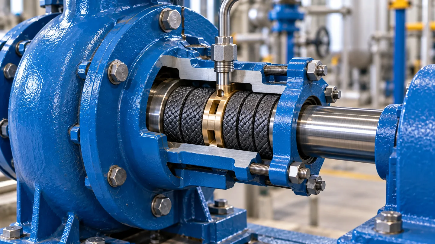
In gland packing systems, a lantern ring is the open annular spacer placed between packing rings so a flush connection can communicate with the shaft or sleeve around the full stuffing-box circumference. Its correct position is set by the flush port and the final seated packing stack—not by a universal ring count.
LANTERN RING PURPOSE
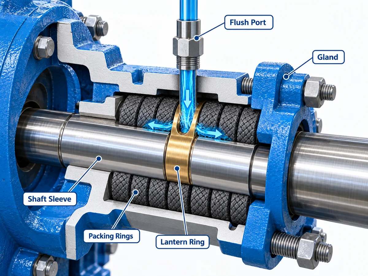
A lantern ring—also called a flush ring or seal-water ring in some packing arrangements—is a rigid or flexible spacer with an annular flow path. It sits inside the pump stuffing box between compression-packing rings and lines up with an external connection in the box wall.
When clean flush liquid enters that connection, the lantern ring gives the liquid a low-resistance path around the shaft or sleeve before it reaches the packing interface. Depending on the service, that flow can help carry heat away, lubricate the rubbing interface and oppose the entry of abrasive or contaminated process fluid.
The lantern ring does not replace the packing and it does not create the primary seal by itself. Reliability still depends on the packing material, shaft or sleeve condition, ring seating, gland-follower alignment and the operating leakage required by the packing system.
POSITION
There is no universal rule that the lantern ring must always follow the second ring, the third ring or sit exactly at the geometric center of the stuffing box. The correct axial location is the one that leaves the lantern-ring groove open to the flush port after the individual packing rings have been seated and the set has taken its initial compression.
Measure where the port opens into the stuffing-box bore from a fixed box reference.
The lantern-ring groove must communicate directly with this opening.Ring thickness is set by the annular space between the box bore and the shaft or sleeve.
Cross-section = (box bore − shaft/sleeve diameter) ÷ 2.Packing rings shorten axially as each ring is seated and the gland takes its initial load.
Do not locate the lantern ring from a loose stack measured on the bench.The final arrangement must leave enough gland-follower engagement for run-in and later adjustment.
Correct flush alignment is not useful if the gland is already at the end of its travel.PACKING ARRANGEMENT
The drawing below shows the logic, not a universal ring count. Packing remains on both sides of the lantern ring, the flush port opens into the lantern-ring zone, and the gland follower loads the outboard end of the set. Different pumps can require different numbers of packing rings before and after the lantern ring.
ALIGNMENT
| Condition | What happens in the box | Likely evidence | Corrective check |
|---|---|---|---|
| Ring centered on the port | Flush enters the lantern-ring groove and can move around the shaft or sleeve. | Stable flush response, controllable leakage and normal temperature for the service. | Confirm again after the set has seated and the gland has moved during run-in. |
| Ring too deep | The port opens mainly against packing instead of the lantern-ring flow area. | Weak or uneven flush effect, heat, solids ingress or short packing life. | Recalculate the stack from the measured port location and installed ring thickness. |
| Ring too far outboard | The flow path is partly covered by the upper packing ring. | Flush appears available externally but does not reach the intended interface reliably. | Check actual seated ring heights and follower position rather than nominal ring count. |
| Flush path blocked | The ring may be positioned correctly but debris, scale or a restricted line prevents flow. | Rising packing temperature, contaminated leakage or rapid sleeve/packing wear. | Verify the complete line, port and lantern-ring passage before repacking again. |
| Follower near end of travel | The stack geometry may be wrong even if the lantern ring initially lines up. | Little adjustment range remains after start-up or leakage cannot be controlled evenly. | Confirm usable box depth, total installed stack height and gland engagement. |
FLUSH PATH
The lantern ring is only the distribution point. The flush system still has to deliver suitable fluid to the ring under operating conditions. For exclusion service, the pressure relationship should be based on the local stuffing-box pressure and the pump or system requirements—not assumed from discharge pressure alone.
For an external exclusion flush, a common field starting point is about 15 psi (approximately 1 bar) above the local stuffing-box pressure. Treat that differential as a starting rule, not a universal setpoint: the pump and packing-system instructions take priority, and excessive flush pressure can increase leakage, packing load or process dilution.
INSTALLATION CHECK
Start with dimensions, not a remembered packing arrangement. Measure the stuffing-box depth, shaft or sleeve diameter, box bore and the axial position of the flush-port opening. Inspect the bore and rotating surface before new packing is installed.
Seat packing rings individually. This matters because the first rings cannot be reliably compressed into their final position by tightening only the gland follower after the whole set is installed.
As the stack approaches the flush port, verify the lantern-ring position against the actual opening. A probe through the disconnected flush connection can confirm that the port communicates with the ring, provided the equipment is safely isolated and the probe cannot damage the box or components.
After the remaining rings and gland follower are installed, establish the required flush condition before operation where the arrangement depends on an external flush. Recheck alignment, leakage and temperature after the packing has run in. See the full pump packing installation guide for ring cutting, seating and gland adjustment.
MAINTENANCE
During a full repack, remove the lantern ring and the packing below it rather than replacing only the accessible outboard rings. A ring that has moved off-axis, packed with solids or worn into the bore can bind deep in the stuffing box; leaving it in place also hides the condition of the inboard packing and can preserve a misaligned flush path.
Use the extraction method intended for the installed ring. Solid rings may have manufacturer-provided puller or extraction features, while split or flexible ring designs can simplify service where the application permits them. Avoid prying against or scoring the shaft sleeve and stuffing-box bore. Once removed, inspect the lantern-ring passages for scale or solids and check the ring for axial wear, distortion and evidence that the flush port was no longer aligned.
RING COUNT
References often describe arrangements such as two packing rings, then a lantern ring, then three packing rings—or the reverse. Those patterns are useful shorthand, but the pump geometry decides whether they are correct. The flush port must still intersect the lantern ring after the set is seated.
A possible five-ring packing arrangement where two inboard rings place the lantern ring at the flush connection. It is not automatically correct for every five-ring box.
Another common arrangement when the port sits farther from the bottom of the box. Again, the measured port location controls the choice.
Some engineered conversions use a close-fitting throat or restriction bushing with an integrated flush passage. This can reduce the number of packing rings and remove a free lantern ring that might shift as the packing consolidates. The bushing changes box depth, clearances and pressure behavior, so recalculate the stack and verify the conversion for the service rather than treating it as a drop-in substitute.
CONSTRUCTION
The ring needs adequate stiffness, chemical compatibility, temperature capability and dimensional stability for the service. Select the ring material from temperature, chemistry, stiffness, wear and fit requirements.
Bronze, stainless steel and other suitable alloys can provide a rigid, dimensionally stable flow ring where corrosion and service conditions permit.
Inspect reusable rings for wear, distortion, corrosion and blocked passages before reinstalling.PTFE, PEEK and other engineered materials can reduce weight and offer useful chemical or temperature properties in suitable applications.
Material limits and fit still have to match the actual duty.Some designs can be opened, cut or fitted around the shaft where a solid ring would be difficult to install during maintenance.
The installed shape must still create a continuous flow path around the shaft or sleeve.Some engineered arrangements combine flushing and restriction functions to reduce solids ingress or control the pressure environment near the packing.
Treat these as system components; do not substitute them solely by matching outside dimensions.CHEMISTRY & TEMPERATURE SCREENING
Material selection needs more than a generic pH value. Chemical identity, concentration, temperature, pressure, ring grade and mechanical load can change compatibility. The ranges below are screening guidance for common lantern-ring materials, not universal design limits.
| Material | Chemical guidance | Temperature guidance | Main caution |
|---|---|---|---|
| PTFE | Very broad chemical resistance. A typical screening range is about pH 0.5–13.5 near 23 °C (73 °F), but the actual chemical and concentration still need verification. | Common virgin-PTFE guidance reaches about 260 °C (500 °F); pressure, speed, fit and compound can lower the practical limit. | Excellent corrosion resistance, but creep and deformation under sustained load can affect fit and alignment. |
| PEEK | Broad chemical resistance with a similar pH screening range of about 0.5–13.5 near 23 °C (73 °F). Strong acids and actual concentration/temperature require grade-specific checking. | Representative PEEK grades are commonly rated around 250–260 °C (482–500 °F) for continuous service, depending on grade and loading. | Higher stiffness than PTFE, but compatibility can change sharply with aggressive chemicals at elevated temperature. |
| Bronze | No single reliable pH range applies to all bronze alloys. Suitability depends on alloy, chemical species, concentration and dissolved contaminants. | Alloy- and application-dependent; use the specific bronze grade and service data rather than a generic temperature number. | Ammonia, oxidizing acids, chlorides and some sulfur-bearing media can be problematic for particular copper alloys. |
| Stainless steel | Grade-specific rather than pH-only. Verify the actual fluid, chloride content, concentration and cleaning chemicals against the selected stainless grade. | Grade- and application-dependent; corrosion resistance can fall before the metal reaches its mechanical temperature limit. | Chloride pitting and stress-corrosion cracking depend strongly on grade, temperature and concentration. |
Selection rule: verify the exact chemical, concentration, operating temperature, local pressure and material grade before specifying a lantern ring. Use pump/OEM and material-supplier limits where they are more restrictive.
APPLICATION
A lantern ring is useful when the packing arrangement requires an internal distribution point for flush, barrier or seal water. Some services use product lubrication, different environmental controls, restriction devices or packing systems that do not require a conventional lantern ring. Use the pump arrangement, measured stuffing-box geometry and actual service conditions to determine whether a lantern ring is required.
| Question | If the answer is yes | If the answer is no | What to verify |
|---|---|---|---|
| Is an external flush required? | A lantern ring may be the intended distribution point. | A conventional lantern ring may add no benefit. | Pump/OEM arrangement and packing-system requirement. |
| Is the process abrasive or contaminated? | A clean exclusion flush may protect the packing and sleeve. | Cooling or lubrication may be the main reason for flush, if required at all. | Local box pressure, solids load and acceptable process dilution. |
| Has the box hardware been modified? | Recalculate ring count and lantern-ring position from the new geometry. | Still confirm dimensions during repacking; wear and prior repairs can change fit. | Depth, bore, sleeve diameter, bushing length and follower travel. |
| Is failure repeating after repacking? | Check alignment, flush continuity, runout and hardware before changing packing again. | Continue normal inspection and run-in monitoring. | Use the troubleshooting sequence to separate packing symptoms from mechanical causes. |
Do not select the lantern-ring position from ring count alone. Measure the stuffing box, seat each packing ring, align the lantern-ring flow area with the flush port, preserve gland-follower travel, and confirm the flush still reaches the ring after run-in.