PUMP PACKING

COMPRESSION PACKING REFERENCE

PUMP PACKING TROUBLESHOOTING

Leakage, Heat, Sleeve Wear & Short Packing Life

Do not treat every packing problem by tightening the gland. Excessive leakage, overheating, sleeve wear and short packing life can originate in the packing set, installation, stuffing-box hardware, flush system or pump condition. Diagnose the symptom before changing gland load.

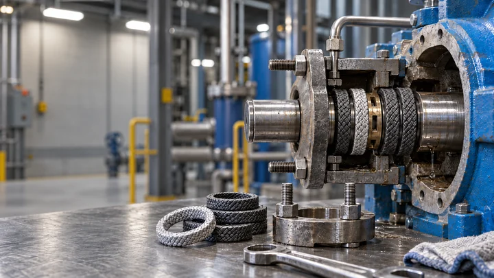
Open pump stuffing box with shaft, packing rings, lantern ring and gland hardware during troubleshooting inspection

DIAGNOSTIC METHOD

TREAT THE SYMPTOM AS EVIDENCE, NOT THE ROOT CAUSE

Leakage, temperature and wear reflect the condition of the complete sealing system. A gland adjustment changes compression, but it does not correct a grooved sleeve, blocked flush path, misplaced lantern ring, excessive runout, poor ring seating or a packing material that is wrong for the duty.

Start with what changed and when it changed. Record leakage pattern, stuffing-box temperature trend, run time, gland position, flush condition, sleeve condition and any process or speed change. A new set that never stabilizes after installation should be investigated differently from a set that ran normally for months and then deteriorated.

Separate cause from consequence. Hot packing can harden and leak; excessive leakage can carry solids into the set; repeated tightening can then increase friction and accelerate sleeve wear. The last symptom observed may be a consequence of an earlier fault, not the original cause.

Compare the problem with the machine's previous stable condition. A change in leakage on only one side points in a different direction from uniform leakage around the follower, while a temperature rise immediately after adjustment is stronger evidence of excess compression than a slow rise associated with a deteriorating flush supply.

Keep removed rings in order during inspection. Differences between the inboard, lantern-ring and gland-side rings often show where heat, solids, extrusion or uneven compression entered the set. Repeating damage at the same axial or circumferential position should direct attention to the adjacent hardware or fluid path.

FAULT DIAGNOSIS

PUMP PACKING TROUBLESHOOTING BY SYMPTOM

Identify the leakage path as well as the amount. Controlled leakage at the shaft/packing ID can provide lubrication and heat removal in many braided-packing arrangements; leakage bypassing the packing at the OD/stuffing-box bore points to a different sealing path. The required leakage condition depends on the packing and stuffing-box arrangement.

SymptomLikely causesCheck firstCorrective direction
Excessive leakageInsufficient gland load, poor ring fit or joints, worn sleeve, runout, solids under the packing, damaged or consolidated ringsFollower position, leakage distribution, ring fit, sleeve surface and mechanical movementRestore even loading and correct the installation or hardware cause before increasing gland load repeatedly
Air ingress / loss of primeLoose or damaged packing, poor ring fit, worn sleeve, or inadequate sealing-liquid pressure where the stuffing box operates below atmospheric pressureWhether the stuffing box is under vacuum, packing condition, sleeve surface and any sealing-liquid pathRestore packing fit and the required sealing-liquid condition; correct worn hardware or other air-leak paths before further adjustment
Very low leakage with rising heatOver-compression, blocked or inadequate flush where fitted, dry start, high friction, packing unsuited to speed or serviceRecent gland adjustments, temperature trend and the flush path where fittedReduce the friction-driving condition and re-establish the cooling/lubrication path instead of tightening further
Short packing lifeWrong material or construction, abrasive solids, high surface speed, sleeve damage, pump movement, poor installation or unstable process conditionsFailure surface of each removed ring, actual duty and hardware conditionChange the root cause before installing the same packing again
Sleeve or shaft wearAbrasive solids, rough or hard packing contact, excessive gland load, poor flush, damaged sleeve surfaceWear pattern, solids path, packing composition and flush qualityCorrect solids exclusion, surface condition and packing selection rather than using gland load to seal across a groove
One-sided leakage / uneven compressionCocked follower, shaft offset or runout, poor ring seating, distorted box or uneven nut adjustmentFollower gap around the circumference, shaft movement and ring compression patternSquare the gland and correct the mechanical or seating problem; do not pull one nut down harder to mask it
Packing extrusionExcessive clearances at gland, throat or lantern ring, high pressure, weak support ring or unsuitable packing densityWhere the extrusion occurred and the adjacent hardware clearanceRestore the required clearance/support geometry and confirm the packing is suitable for actual pressure
Solids embedded in packingDirty flush, loss of flush differential, process ingress, loss of gland load or an ineffective lantern-ring pathWhich rings contain solids, flush cleanliness and whether clean fluid reaches the packing IDRestore clean, continuous solids exclusion and verify lantern-ring alignment after compression
Soft, brittle or chemically changed ringsChemical incompatibility with process media, cleaning fluids, temperature or oxidation environmentMaterial appearance compared with unused packing and all fluids that contacted the setRe-select the packing material for the real chemical and temperature exposure

FAILURE PATTERNS

WHAT THE REMOVED PACKING CAN TELL YOU

Inspect the complete ring set before discarding it. Ring order, inner and outer surfaces, joint condition and differences in compression can separate a packing-selection problem from a flush, clearance, installation or pump-condition problem.

Glazed or hardened running surface

A smooth, polished or hardened ID can indicate excessive heat, inadequate lubrication/cooling, high friction or a surface-speed/material mismatch.

Review temperature history, leakage/flush condition, surface speed and gland load.

Extruded edges or missing material

Packing forced into a clearance points toward excessive gaps, pressure, poor support or packing that lacks the required extrusion resistance.

Match the extrusion location to the gland, throat or lantern-ring clearance beside it.

Abrasive cuts and embedded solids

Cut fibers, eroded surfaces or trapped particles show that abrasive material is reaching the packing contact zone.

Trace the solids path through process ingress, dirty flush or loss of flush differential.

Uneven radial compression

One side of a ring flattened more than the opposite side can indicate a cocked gland, runout, deflection, poor seating or distorted hardware.

Measure the pattern around the ring before assuming the packing itself is defective.

Dry, burnt or heat-damaged ID

Dry rubbing or thermal damage indicates that friction exceeded the ability of leakage or flush to remove heat from the interface.

Do not use additional gland load as the first response to a hot packing set.

Failure concentrated at one ring

Localized damage can correlate with a flush port, misplaced lantern ring, sleeve groove, pressure transition or a ring that was cut or seated differently.

Keep the rings in removal order so the damage can be matched to its position in the stuffing box.
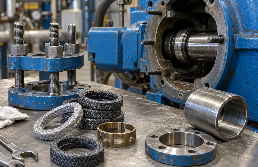
Removed compression packing rings, gland hardware, lantern ring and shaft sleeve arranged beside an open pump stuffing box for inspection

WHEN THE PROBLEM STARTED

TIMING NARROWS THE FAILURE MODE

Immediately after repackingPrioritize ring size, cutting, seating, joint staggering, initial gland load and lantern-ring position.
After a gland adjustmentCheck compression balance, temperature rise and loss of the required leakage/flush cooling path.
After weeks or monthsLook for packing consolidation, sleeve wear, solids accumulation, loss of flush or gradual pump-condition change.
After a process changeRecheck chemistry, solids, temperature, pressure and speed against the packing selection and flush arrangement.
Only at certain operating pointsInvestigate stuffing-box pressure, shaft movement, vibration, cavitation or flush differential across the operating range.

ROOT-CAUSE CHECK

WHEN REPACKING ALONE WILL NOT FIX THE PROBLEM

A new packing set can restore sealing only when the surrounding hardware and operating conditions allow it to establish stable contact. Repeatedly replacing packing without correcting the cause usually produces the same failure pattern.

Damaged rotating surface

Deep grooves, scoring, corrosion or excessive runout continually disturb packing contact and can accelerate leakage and fiber wear.

Wrong clearances or follower geometry

Excessive gaps promote extrusion; a follower that cannot enter squarely creates uneven compression through the set.

Flush cannot reach the packing

A blocked port, misplaced lantern ring, dirty supply or inadequate differential defeats cooling and solids exclusion even when the packing is new.

DIAGNOSTIC SEQUENCE

A PRACTICAL TROUBLESHOOTING ORDER

Change one class of variable at a time. Confirm the symptom first, then gland and flush condition, mechanical hardware, installation evidence and finally packing selection.

Before adjusting anything, record leakage distribution, temperature, follower position, flush status and operating point. Use these readings as the baseline for every subsequent adjustment.

Do not judge a correction from leakage alone. Lower leakage accompanied by rising stuffing-box temperature or loss of cooling is not a successful adjustment.

After each meaningful change, recheck the same observations before changing something else. If the same failure pattern returns with a correctly installed new set, investigate sleeve condition, clearances, alignment, flush and operating conditions.

Reassess packing material or construction only after actual chemistry, temperature, pressure, speed, solids and hardware condition have been confirmed.

1
Record the symptomLeakage pattern, temperature trend, run time and the exact point when behavior changed.
2
Check gland loadingConfirm the follower is square, both sides are adjusted evenly and usable travel remains.
3
Verify the flush path where fittedWhere external flush or sealing liquid is used, confirm cleanliness, continuity, differential and communication with the lantern-ring zone.
4
Inspect the hardwareCheck sleeve/shaft surface, runout, bore, gland and clearances before blaming the packing.
5
Read the removed ringsKeep them in order and compare wear, solids, heat damage, extrusion and compression around each ring.
6
Review installationConfirm measured packing size, cut length, separate seating, staggered joints and final lantern-ring location.
7
Reassess packing selectionCompare material and construction with actual chemistry, temperature, speed, pressure and abrasion.
INSTALLATIONRING FIT & GLAND SET-UP

Review cutting, seating, joint staggering, lantern-ring placement and controlled start-up.

Open installation →
HARDWARESTUFFING BOX

Check bore, sleeve, follower travel, clearances, lantern ring and flush geometry.

Open stuffing box →
SELECTIONPACKING MATERIALS

Compare graphite, carbon, PTFE, aramid and synthetic fibers against the actual duty.

Open materials →
CONSTRUCTIONPACKING TYPES

Compare braid constructions, formed rings and hybrid packing arrangements.

Open types →